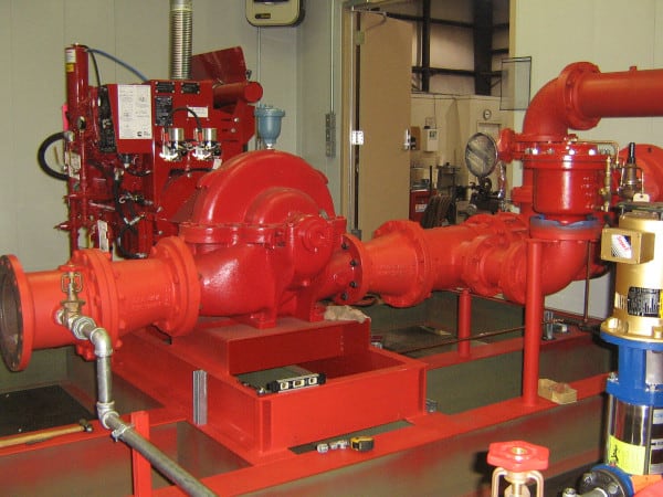
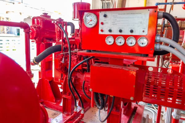
Fire pumps are a vital part of many fire sprinkler systems, driving the necessary pressure and volume to keep water flowing when it isn’t generated by the water supply. In such cases, sprinklers won’t function correctly without a pump—and the midst of a fire isn’t the time to figure out that your fire pump isn’t working properly. The fire pump flow test is a crucial annual requirement to ensure that the system works in an emergency.
In this blog, we begin our examination of the National Fire Protection Association (NFPA) rules and best practices for annually testing your fire pump. Stay tuned for part two, which will complete our in-depth look at fire pump annual testing.
Are you looking to buy parts for your building’s sprinkler system? Feel free to browse our selection of sprinkler system components and accessories, including commercial and residential sprinkler heads, installation tools, fire extinguishers, heavy-duty head guards that protect sprinklers from accidental damage or vandalism, and so much more.
With costs that start at $20,000 and can surpass $1 million when suction tanks are required, fire pumps are the single-most expensive component of a water-based sprinkler system—and failing to maintain them properly will significantly shorten their useful lives.
High-rise buildings, where water must be able to defy gravity and surge up tens and even hundreds of feet to reach the top floors within seconds, are especially at risk without a fully operational pump. Pumps are also critical for buildings that supply their sprinkler systems through water storage tanks which don’t generate gravity-fed water pressure, and buildings where the municipal supply doesn’t create enough pressure on its own.
Annual fire pump tests are key to properly maintaining the equipment, identifying deterioration of the pump or impairments to the water supply before they develop into bigger problems. The 2017 edition of NFPA 25: Standard for the Inspection, Testing, and Maintenance of Water-Based Fire Protection Systems addresses minimum testing requirements for fire pumps. Additional guidelines are available in NFPA 20: Standard for the Installation of Stationary Pumps for Fire Protection, which aims to ensure that systems will work as intended to deliver adequate and reliable water supplies.
Fire pumps that boost pressure on municipal water supplies are usually electric, and diesel engines are most common in private water supplies. Steam turbine engine-driven pumps can still be found in some older systems, but tend to be rare. For the most part, all fire pumps require the same annual tests, although the extra complexity of diesel engine-driven pumps demands some additional testing.

Fire pump testing is complex and must be performed by qualified professionals. However, NFPA 25 charges the property owner with maintaining complete written reports of fire pump test results (8.4). At a minimum, the report must include (8.4.1.1):
The annual fire pump flow test is a full test of a pump’s capabilities and is arguably the most critical test. It is conducted once a year to measure flow and pressure and make sure the fire pump is ready to respond to a call to service. It can also uncover any problems with the pump’s water supply, such as closed valves or obstructions between the supply and the equipment.
During the testing period, the fire pump is temporarily taken offline, so it’s important that nothing beyond “normal operations” are conducted on a property while this occurs to minimize risk to occupants. Since the pump will be operating at extreme conditions during the test, it’s essential to take careful safety precautions, such as wearing protective gear, testing in properly ventilated areas, only using hoses that have passed a service test within the past 12 months, and shutting down discharges before changing nozzles.
Test results should not deviate by more than five percent from the initial acceptance test performed right after the fire pump was installed or the pressures indicated on its nameplate. If that information isn’t available, a satisfactory test should deliver:
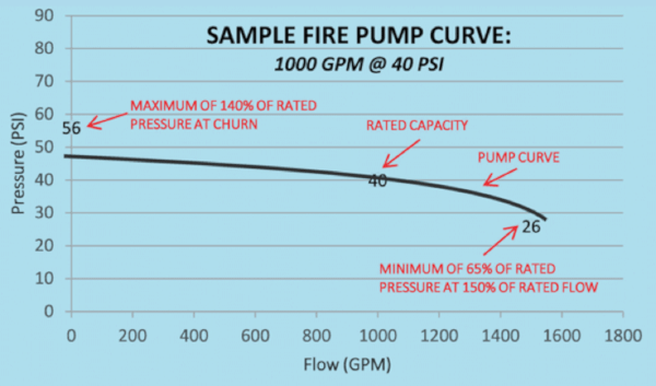
Let’s dig into what that means: Fire pumps are designed to produce specific flow rates and pressures. Minimum, rated, and peak loads refer to the amount of water flow that the pump will allow. Rated capacity occurs when the pump is discharging water at its specified pressure. The churn pressure is a measure of the pressure the pump delivers when it is running without water flowing through it.
The more water that’s flowing, the more work the pump is performing, and the less pressure that’s available. A well-performing pump must produce not less than 65 percent of rated pressure when flowing water at a rate of 150 percent of rated flow. While NFPA 20 should be consulted for more details about fire pump flow testing, read on for an overview of what’s required by NFPA 25:
From the 2017 edition of NFPA 25
8.3.3* Annual Flow Testing.
8.3.3.1* An annual test of each pump assembly shall be conducted by qualified personnel under no-flow (churn), rated flow, and 150 percent of the pump rated capacity flow of the fire pump by controlling the quantity of water discharged through approved test devices.
8.3.3.1.1 If available suction supplies do not allow flowing of 150 percent of the rated pump capacity, the fire pump shall be tested to the maximum allowable discharge.
Watch this video for step-by-step instructions for performing an annual fire pump flow test:
Acceptable configurations for fire pump flow tests
Flow tests are usually performed by attaching hoses to the pump’s discharge test header and running them to a safe location where flowing water won’t cause damage. Flowing water exerts significant force, so make sure the hoses are laid out neatly and securely anchored to ensure safe operation. Under no circumstances should anyone—even a trained firefighter—hold any hose during a flow test. T-shaped hose monsters that counteract the force of the water are safer to use during testing than hose nozzles, which can come loose.
Attaching the hoses to playpipes securely anchored to a truck or trailer is another option. Playpipes are remarkably smooth, long pipes with a nozzle at the end that straighten streams of water while reducing turbulence. Playpipes attached directly to the pump test header may also allow for safe water discharge, as long as there is a clear path for water streams and ground run-off that won’t damage landscaping or equipment.
No matter what discharge method you choose, water streams or inadequate drainage can damage the discharge area. Many jurisdictions have specific requirements for the disposal of test water; it’s essential to find out what they are and follow them.
From the 2017 edition of NFPA 25
8.3.3.6 The annual test shall be conducted as follows:
(1) The arrangement described in 8.3.3.6.1 or 8.3.3.6.2 shall be used at a minimum of every third year.
(2)* The arrangement described in 8.3.3.6.3 shall be permitted to be used two out of every three years.
8.3.3.6.1 Use of Pump Discharge via Hose Streams.
8.3.3.6.1.1 Pump suction and discharge pressures and the flow measurements of each hose stream shall determine the total pump output.
8.3.3.6.1.2* Care shall be taken to minimize any water damage caused by the high volume of water discharging during the test.
8.3.3.6.2 Use of Pump Discharge via Bypass Flowmeter to Drain or Suction Reservoir. Pump suction and discharge pressures and the flowmeter measurements shall determine the total pump output.
A flow loop is a piping configuration that enables fire pump testing without flowing water out of the sprinkler system. Instead, it’s sent through a flow meter, returned to the suction side of the fire pump, and cycled back through the system. Flowmeter devices make it possible to perform the annual flow test without flowing large amounts of water by measuring the amount of water flow in a recirculating system.
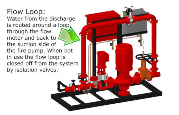
There are some drawbacks to this testing method. For one, it doesn’t test whether the water available from the suction supply meets the requirements of NFPA 25, section 8.1.6:
8.1.6 Energy Source. The energy sources for the pump driver shall supply the necessary brake horsepower of the driver so that the pump meets system demand.
Another risk is that the flow meter can go out of calibration. That said, flow loops also don’t waste water, which can be a major benefit for high-capacity pumps where water waste can quickly reach thousands of gallons and transform discharge sites into swimming pools. When flow loops are used, they are typically paired with test headers to ensure proper calibration of the flow meter.
8.3.3.6.3 Use of Pump Discharge via Bypass Flowmeter to Pump Suction (Closed-Loop Metering).
8.3.3.6.3.1 Pump suction and discharge pressures and the flowmeter measurements shall determine the total pump output.
8.3.3.6.3.2 When testing includes recirculating water back to the fire pump suction, the temperature of the recirculating water shall be monitored to verify that it remains below temperatures that could result in equipment damage as defined by the pump and engine manufacturers.
8.3.3.6.3.3 If the test results are not consistent with the previous annual test, the test shall be repeated using the test arrangement described in 8.3.3.6.3.1.
8.3.3.6.3.4 If testing in accordance with 8.3.3.6.3.1 is not possible, a flowmeter calibration shall be performed and the test shall be repeated.
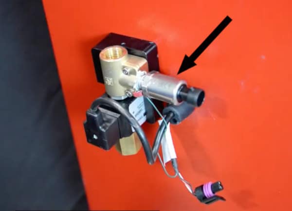
High-quality test equipment is essential for fire pump annual flow tests. For best results, everything that’s used should bear a calibration sticker attesting to calibration within the past year by an approved calibration facility. If possible, the calibration certificate should also be available for inspection.
The gauges and transducers—a device that converts energy into an electrical signal—used during the flow test must be unique to the test because they need to be incredibly accurate. Their measurements need to be within +/- 1 percent to accurately identify trends over time. The standard gauges on the fire pump can’t be used during the test because they aren’t precise enough.
Equipment other than pressure gauges, such as tachometers and ammeters, should be calibrated to the manufacturer’s specifications. Readings from equipment with this level of accuracy and calibration can be used without adjustment.
To avoid costly delays, it’s wise to have a spare set of equipment available during the test in case any piece of test equipment fails.
From the 2017 edition of NFPA 25
8.3.3.2 Test Equipment.
8.3.3.2.1 Voltage and amperage readings on fire pump controllers that meet the following criteria shall be permitted in lieu of calibrated voltage and/or amperage meters:
(1) The fire pump controller shall have been factory calibrated and adjusted to ±3 percent.
(2) The voltage reading shall be within 5 percent of the rated voltage.
8.3.3.2.2 Except as permitted in 8.3.3.2.1, calibrated test equipment shall be provided to determine net pump pressures, rate of flow through the pump, volts and ampere, and speed.
8.3.3.2.2.1 Calibrated gauges, transducers, and other devices used for measurement during the test shall be used and bear a label with the latest date of calibration.
8.3.3.2.2.2 Gauges, transducers, and other devices, with the exception of flow meters, used for measurement during the test shall be calibrated a minimum of annually to an accuracy level of ±1 percent.
8.3.3.2.2.3 Flow meters shall be calibrated annually to an accuracy level of ±3 percent.
8.3.3.3 Discharge and sensing orifices that can be visually observed without disassembling equipment, piping, or valves shall be visually inspected and be free of damage and obstructions that could affect the accuracy of the measurement.
8.3.3.4 The sensing/measuring elements in a flow meter shall be calibrated in accordance with 8.3.3.2.
8.3.3.5 Discharge orifices shall be listed or constructed to a recognized standard with a known discharge coefficient.
During a flow test, pressure readings are taken as the pump is run through various stages, plotted on hydraulic graph paper, and compared to factory specifications and test results from previous years. Certain digital ITM platforms can plot this information within ready-made software and automatically generate reports.
If there is a significant reduction in the pump’s rated performance compared to what’s shown on the fire pump nameplate or original acceptance test curve, an investigation is needed to determine necessary corrections and repairs.
From the 2017 edition of NFPA 25
8.3.3.7 The pertinent visual observations, measurements, and adjustments specified in the following checklists shall be conducted annually while the pump is running and flowing water under the specified output condition:
(1) At no-flow condition (churn), the procedure is as follows:
(a) Inspect the circulation relief valve for operation to discharge water.
(b) Inspect the pressure relief valve (if installed) for proper operation.
(2) At each flow condition, the procedure is as follows:
(a) Record the electric motor voltage and current (all lines).
(b) Record the pump speed in rpm.
(c) Record the simultaneous (approximately) readings of pump suction and discharge pressures and pump discharge flow.
(3)* For electric motor–driven pumps, do not shut down the pump until it has run for 10 minutes.
(4) For diesel motor–driven pumps, do not shut down the pump until it has run for 30 minutes.
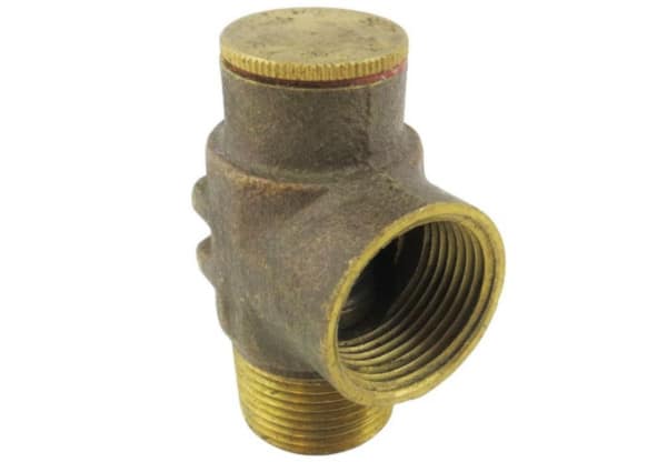
A pressure relief valve is a safety device designed to discharge a large flow of water when the pressure in a system exceeds prescribed limits. However, an opened pressure relief valve will impact flow test results by discharging water that’s not measured by the recording device during the test.
It may become necessary to temporarily close the pressure relief valve to achieve satisfactory fire pump test results. At the end of the flow test, the pressure relief valve can be readjusted to relieve pressure that’s greater than the normal operating pressure of the system.
If the valve is opened during flowing conditions because the pressure is too high for the fire pump’s components, the discharge control valve should be closed before closing the pressure relief valve to protect the system from damage due to an overpressure event. The discharge valve can be re-opened after the test.
From the 2017 edition of NFPA 25
8.3.3.8* For installations having a pressure relief valve, the operation of the relief valve shall be closely observed during each flow condition to determine whether the pump discharge pressure exceeds the normal operating pressure of the system components.
8.3.3.8.1* The pressure relief valve shall also be observed during each flow condition to determine whether the pressure relief valve closes at the proper pressure.
8.3.3.8.2 The pressure relief valve shall be closed during flow conditions if necessary to achieve minimum rated characteristics for the pump and reset to normal position at the conclusion of the pump test.
8.3.3.8.2.1 When it is necessary to close the relief valve to achieve minimum rated characteristics for the pump, the pump discharge control valve shall be closed if the pump churn pressure exceeds the system rated pressure.
8.3.3.8.3 When pressure relief valves are piped back to the fire pump suction, the temperature of the recirculating water shall be monitored to verify that it remains below temperatures that could result in equipment damage as defined by the pump and engine manufacturers.
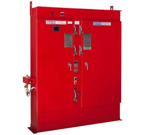
Transfer switches route two sources of power to the fire pump motor. Generally, one is a utility source connected to the normal side of the transfer switch, and the other is a standby emergency generator connected to the emergency side. NFPA requires a second source of power for fire pumps when the building height exceeds the pumping capacity of the fire department or when the authority having jurisdiction (AHJ) deems the utility power at the location unreliable.
From the 2017 edition of NFPA 25
8.3.6.2 Automatic transfer switches shall be tested routinely and exercised in accordance with NFPA 110.
8.3.3.9 For installations having an automatic transfer switch, the following test shall be performed to ensure that the over‐current protective devices (i.e., fuses or circuit breakers) do not open:
(1) Simulate a power failure condition while the pump is operating at peak load.
(2) Verify that the transfer switch transfers power to the alternate power source.
(3) While the pump is operating at peak load and alternate power, record the voltage, amperage, rpm, suction pressure, discharge pressure, and flow rate and include in the pump test results.
(4) Verify that the pump continues to perform at peak horse‐power load on the alternate power source for a minimum of 2 minutes.
(5) Remove the power failure condition and verify that, after a time delay, the pump is reconnected to the normal power source.
Flow tests also test pump alarms, but it’s not the test’s intent to verify that all alarm conditions required by NFPA 20—including low oil pressure, high coolant temperature, and engine overspeed—transmit individually to a remote location. Instead, the flow test only aims to individually verify each alarm, when provided, at the fire pump controller.
8.3.3.10* Alarm conditions shall be simulated by activating alarm circuits at alarm sensor locations, and all such local or remote alarm indicating devices (visual and audible) shall be observed for operation.
8.3.3.10.1 Alarm conditions that require the controller to be opened in order to create or simulate the condition shall be tested by qualified personnel wearing appropriate protective equipment.
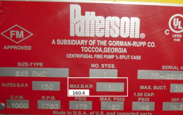
Once the flow test is completed, the new test plot should be compared with results from the original acceptance test conducted after the fire pump was installed. If those results aren’t available, the original factory curve can also be used as a baseline for performance comparison. The factory curve should be available in operation or maintenance manuals, or from the fire pump manufacturer. The nameplate attached to the fire pump or its base also contains the necessary data, including rated capacity, churn pressure, and 150 percent of rated capacity.
To pass the flow test, a fire pump must be capable of supplying the full system demand, which is provided by the property owner. The performance at each flow and pressure point also must not be less than 95 percent of the pump’s nameplate data or the pump’s original unadjusted field test curve.
The graph of a favorable fire pump flow test should appear as a gradually sloping curve that falls to the right. But read this carefully: reports that have not been evaluated or compared to previous test results are not complete because they don’t provide a full picture of pump performance.
Even so, keep this in mind as you evaluate the results: the original acceptance test results sometimes exceed the minimum acceptable pump requirements indicated by the rated characteristics for the pump. While a reduction in output is usually a matter of concern, A.8.3.7.1 of NFPA 25 warns that it should be evaluated in light of meeting the pump’s rated characteristics.
From the 2017 edition of NFPA 25
8.3.7 Test Results and Evaluation.
8.3.7.1* Data Interpretation.
8.3.7.1.1 The interpretation of the flow test performance relative to the manufacturer’s performance shall be the basis for determining performance of the pump assembly.
8.3.7.1.2 Qualified individuals shall interpret the test results.
8.3.7.1.3 Where applicable, speed and velocity pressure adjustments shall be applied to the net pressure and flow data obtained to determine compliance with 8.3.7.2.3(2).
8.3.7.2 Evaluation of Fire Pump Test Results.
8.3.7.2.1 The fire pump test results shall be evaluated in accordance with 8.3.7.2.2 through 8.3.7.2.9.
8.3.7.2.2 Increasing the engine speed beyond the rated speed of the pump shall not be permitted as a method for meeting the rated pump performance.
8.3.7.2.3 The fire pump test results shall be considered acceptable if both of the following conditions are satisfied:
(1) Fire pump can supply the full system demand as provided by the owner.
(2)* Fire pump test results are no less than 95 percent of the flow rates and pressures at each point for either a or b:
(a) Original unadjusted field test curve
(b) Fire pump nameplate
The graph below shows a sample fire pump curve. When reading from left to right, facilitiesnet explains that field results from an NFPA 25-compliant fire pump will plot a churn pressure value below the first point marked. The curve will then pass through or very close to the second point, and the final value will appear above the third point.
Fire pumps are required when a sprinkler system’s native water supply can’t provide enough pressure to meet its hydraulic design requirements. If the fire pump fails and can’t maintain the system’s water pressure during a fire, people and property are at risk. Comprehensive annual testing keeps fire pumps in working order, alerting ITM professionals and property owners to problems that must be fixed before emergencies happen.
Check out part two of our fire pump testing series, which completes our in-depth look at the annual tests.
Feel free to browse our selection of sprinkler system components and accessories, including commercial and residential sprinkler heads, installation tools, fire extinguishers, heavy-duty head guards that protect sprinklers from accidental damage or vandalism, and so much more.
If you can’t find an item or otherwise need help, give us a call at 888.361.6662 or email support@qrfs.com.